Well, I've gone and done it. I can safely say I'm now a full blown 3D printing enthusiast because... I built a Voron. Many turns of an allen key later, I put together what is widely considered the cream of completely open-source, DIY 3D printers: the Voron 2.4. Here's what my build experience was like.
I'll start off by saying this, a Voron is unlike any other 3D printer. It is not mass-produced in any capacity by any one company. What the Voron Design group actually provides is the plans, directions, and bill-of-materials required to source parts and assemble this printer from the ground up. It's also not like most consumer printers where there is typically some assembly required. You may screw in a gantry or two and plug some wires in, but that's it. With a Voron, you're building this printer from basically nothing but individual components. Every single screw requires you to turn it, and every single wire requires you to connect it in the right place.
 |
| This snippet of the V2.4's official BOM is enough to make me want to cry. |
That all requires a bit of electro-mechanical aptitude, but putting the printer together is at least a little more straightforward than acquiring the parts to do so. For a time, the only way to put a Voron printer (and really, most open source 3D printers in general) together was to find all your components on the internet from the bill-of-materials, order them all, wait god-knows how long for them to arrive, and pray they're even correct when they do. And that's before you get into drilling and tapping aluminum extrusions, crimping wire harnesses, and all other manner of tedious shit before you actually start putting things together.
 |
| LDO Motors offers probably the highest quality kit for the V2.4, but you're paying for it. |
Thankfully, there are now kit makers who go through the trouble of sourcing and preparing all the necessary parts, so all that's left for you to do is assemble the thing like a piece of IKEA furniture from hell. The three most prominent kit manufacturers I've delved into are
LDO Motors,
FYSETC, and
Formbot. LDO offers probably the most reputable kit with high quality components and good post purchase support - but they charge quite the premium. FYSETC on the other hand, is apparently quite the opposite. I can't speak from experience, but a lot of the opinions I've seen on the FYSETC kits show a lack of consistency that you don't find on the LDO kits, but they are much cheaper.

Personally, I elected for the Formbot kit. They seem to fall somewhere between LDO and FYSETC in terms of quality and value for money, plus they're the only kit maker I've seen to offer the 250mm size, which is ideal for my space constraints. I also purchased their pre-printed ABS parts, just so I didn't have to struggle doing it all myself on my Ender-3 S1. I paid just over $920 for the 250mm "Pro" kit with the E3D V6 hotend, plus all the ABS parts with expedited shipping, but Formbot offered to upgrade me to the then unreleased "Pro+" kit which included upgraded electronics at no additional cost.
In total, it took a little over two weeks from the time of the order being place for everything to arrive. The main kit arrived seven days from a US warehouse after the order was placed, while the printed parts took sixteen days from China. I suspect there was some additional lead time required for the Pro+ kit's new printed parts, but it wasn't exactly what I'd call "expedited".
But the parts were all very well packaged and neatly organized into foam compartments. Checking over all the pieces before assembly, I found everything to be of good quality. The aluminum extrusions were are all straight with no warping and none of the components were damaged or missing. All the bags were labeled to identify what the parts were for and all the wiring was pre-crimped and labeled as well.
The printed parts I'd say weren't quite up to the same standards as the main kit. The glass filled ABS looks really nice and feels great to the touch, but I found they were a bit over-extruded in some parts. I had to sand down top surfaces and elephants foot on parts that called for flush mating, particularly on the toolhead, gantry, and Z-axis motor mounts. I was also missing some pieces that would've made sense to include given the included components, but I'll touch more on those as I progress through the build.
For tools, I used a set of standard allen keys, a hex driver set, a soldering iron for the heat set inserts, a Dremel, digital calipers, and the sandpaper included in the kit. I primarily followed Voron's official build guide, but also referenced materials from LDO, MagicPheonix, and BigTreeTech regarding some of the deviations from the stock build, especially on the electronics side of things.
Frame
 |
| It's important to check all the extrusions for the frame are the same required length before starting. |
The first and one of the most important parts of the build to get correct, is the frame. The primary goal with the frame is to get it as square as possible, so a flat build surface is required. I used my glass top desk, but something like a glass top stove or a granite countertop would also work. The main thing is just ensuring the surfaces are all flush and not twisting as the screws are tightened, which is pretty easy to do using the blind joint technique utilized to join the corners together.

I held the pieces flush against my desk while I braced the sides against another extrusion to keep them flush and prevent twisting. Since I don't have an engineer's square, I just used the same piece of extrusion to verify the joint was flush and square. I repeated this for every corner, and while constantly rechecking and retightening everything was a pain, my work checked out when I verified the diagonals with a tape measure.
After attaching the bottom frame for the bed, I was left with a nice aluminum cube - that was also the distinct frame of a Voron 2.4. Things were really happening at this point, so I excitedly pressed onward.
Z-rails and Bed
The next step was to attach the four linear rails for the Z-axis. As someone who has never worked with linear rails before, these things are pretty neat. It's a solid steel rail with a bearing filled carriage that's really rigid, but moves very smoothly; not dissimilar to the ball bearing slide rails you'll find on a drawer or filing cabinet. These are often used to replace the old school V-slot wheels you'll find on most 3D printers.
In the case of the Voron 2.4, there's a lot of conflicting information on how to prepare the linear rails before install. The general consensus seems to be to soak them in IPA for a little while to purge out the packaging oils, and then repacking the carriage with grease. What kind of grease is up for debate, but I used standard white lithium grease since it was all I had on hand and it was one of the recommended types.
I soaked the rails in their packaging for about ten minutes before flipping them over and filling the carriage with grease through one of the mounting holes. I was honestly skeptical if I even did all this properly, as the rails seemed to have lost a bit of their smoothness after the process, but I continued on. Formbot unfortunately didn't include centering tools for the linear rails so I had to do my centering with the calipers.

I also went ahead and attached the bottom panel and the bed. Evidently, the material Formbot used to use for this panel was very prone to warping under heat, so they changed it to this really stiff aluminum composite, that's pretty nice looking to boot. I also left the bed attached slightly loose since it's recommended to fully heat it before tightening it down. I did run into an issue where the slots in one of my DIN rails didn't line up with the holes in the bottom panel, so I had to drill a new hole. The rails are also quite sharp where they were cut but thankfully, the kit includes endcaps to keep you or your wires from getting cut.
At this point, none of my printed parts had arrived yet, so I decided to get a jump start on configuring the electronics.
Board Flashing
 |
| BigTreeTech should look into making PC motherboards, because this is seriously nice. |
Most Voron 2.4 builds opt for a BigTreeTech (BTT) Octopus mainboard with a Raspberry Pi to run Klipper firmware. However, Formbot's Pro+ kit is configured with a BTT Manta M8P v1.1 and a CB1 compute module, which effectively combines the the Octopus and Raspberry Pi in terms of functionality on a single board, freeing up internal space, and reducing wiring complexity.
These boards were also partly designed in response to the ongoing shortage of Raspberry Pi hardware, and a lot of brands have taken it to themselves to design effective stand-ins for the popular microcontrollers. The CB1 is BTT's equivalent to the Raspberry Pi Compute Module 4 (though it's closer to the Raspberry Pi 3 in terms of power). It's worth noting that SD cards created for a Raspberry Pi will fail to boot on the CB1 due to bootloader differences, so transferring an existing install isn't exactly straightforward if you plan on moving to a CB1 in the future.
I really have to hand it to BigTreeTech though: the fully decked out Manta M8P is a damn good looking piece of hardware. It's kind of a shame that it's never actually going to be seen beyond the the occasional opening of the printer's electronics bay.
The Manta/CB1 combo is only two thirds of the computing power of the printer though. That final piece is the BTT EBB SB2209 (RP2040), which is the control board for the toolhead. On a stock build, controlling the toolhead requires a whole bundle of wires to be routed from the electronics bay, through several cable chains, to the toolhead. With the EBB, all the control of the toolhead is moved on-board the toolhead itself, and that thick bundle of wiring is reduced to one cable thanks to CANbus.
The task at hand was to set up CANbus and install Klipper on both boards. MagicPheonix offers a
very comprehensive guide on how to do this, so I'll spare you the details, but I had to take into account that their guides use the standard STM32 equipped EBB, not the RP2040 variant, so I had to take that hardware difference into account so I didn't accidentally misconfigure the board.
I also took some time to familiarize myself with the Mainsail web interface and the printer's configuration file. Again, MagicPheonix offers a largely complete
"printer.cfg" file for the Voron 2.4 running a Manta M8P and EBB so I incorporated a good chunk of it into the Voron default configuration for the M8P. Since my board was a v1.1 board, I did have to reconfigure some pins along with all the pins on the EBB since the RP2040 does not share pinouts with the STM32.
This was all fairly obnoxious work, but it was a great way to kill some time before the printer parts arrived. And by the time I was ready to start wiring, my configuration was mostly complete and everything would just be "plug-and-play"... almost. It never does work out that way the first time.
Stealthburner Assembly
 |
| The EBB installed in the Stealthburner's housing. |
But now that the parts arrived, I changed gears to building the centerpiece of the Voron 2.4 - the Stealthburner toolhead. The Stealthburner is comprised of three main components: the Clockwork 2 direct drive extruder, the hotend, and the front shroud. It seems like a pretty complicated piece of kit, even after having messed around with Creality's Sprite extruder for some time, but there really isn't a huge amount of complexity going on here, at least from a pure assembly standpoint. A lot of clever geometry and packaging makes assembly fairly straightforward and maintenance a piece of cake.
 |
| The finished Clockwork 2 extruder. |
The Clockwork 2 extruder ended up being one of those components I needed to sand a fair amount on in order to get he fitment right. The parts from Formbot were simply too over-extruded to get a flush fitment between the two halves, and the filament lock to move freely. I also had to cut down the included spring since it was a little too long for the provided thumbscrew. Beyond that, it went together nicely and it gave me a thorough crash course on installing heat set inserts.
The hotend section houses the E3D V6, it's accompanying thermistor and heater cartridge, and the nozzle fan ducts. This part's geometry will differ based on the exact hotend you opt for, but generally speaking, it was the least involved part of the Stealthburner to assemble. Just route the wires, screw the two halves together, and presto.
That left the front shroud, which houses both fans, LEDs, and the breakout board for the EBB. There's a tiny amount of support removal involved in preparing this piece, plus you get the fun task of hacking up a blower fan to fit inside of the housing. Beyond that, assembly of this piece is pretty straightforward.
This was also the one place I had an issue with Formbot's pre-crimped wiring. The wires for the LEDs were too short, and the connector couldn't reach the header via the normal wire channel. I had to Dremel out a new path for the wires to reach the header through a section of empty space in the shroud, and it did the trick, but that's a bit of an annoying oversight on Formbot's part.
But once it's all together, it's a super neat little package. Well, it's not exactly "little" either. It's a little larger than a can of soda - which is a lot bigger than I thought this thing looked in all the pictures and videos of the Voron 2.4. Granted, I kind of underestimated the size of the whole printer in general. While the 250mm bed size fits my space limitations, it's still roughly 17" wide, 20.5" tall, and 23" inches deep including a spool of filament and the PTFE tube out the back. The 300mm and 350mm versions practically need their own table.
Z-axis Motion System
With the toolhead done, I went to work building the four Z-axis motor mounts and idler assemblies. Once again, I had to sand down over-extruded material on the top surfaces to get these parts fitting flush. Otherwise, the assembly of these blocks was pretty straightforward, with the only real trickiness stemming from ensuring the pulleys were spaced the appropriate distance with calipers.
The motor bracket has it's own simple belt tensioner: the little red lever, that gets pushed in before the screws are tightened down. With the rubber feet in place, they make for an incredibly stable base that doesn't shift around at all. They also stabilize the bottom corners of the frame so they won't be susceptible to twisting anymore and they easily scale with the size of the printer if say, I decide to up the frame size in the future. These are a prime example of some of the really thoughtful engineering that went into this printer's design.
 |
They look like eyes! Eyebrows and everything! Eye-dlers! Get it?
(I didn't make this up. That's actually what they refer to them in the manual.) |
As this is a belt driven Z-axis, we naturally need pulleys on the opposite end of each stepper, and that's where these little idlers with built in tensioners come into play. A similar idler/tensioner combination is used in the front of the printer for the A and B belts on the gantry.
Nevermore Filter
 |
| Stop violence against blower fans. What did they ever do to you? |
Nevermore air filters are one of the most popular Voron upgrades lately, and Formbot was thoughtful enough to include the parts to build your own in it's kit. The downside, was that they made changes to the original Nevermore V5 Duo design that weren't documented at the time I started my build. I was flying blind and frankly, I have no idea why Formbot decided to make these changes.
The build starts off innocently enough by defiling a pair of blower fans to cram into the tight confines of the Nervermore's casing. Where things start to get weird is where magnets would normally be glued into the two halves of the filter - there isn't anywhere to put them. I realized there's actually now two top cavities where the magnets are supposed to be pushed in. That sounds less messy, but the holes were so tight that I needed to hammer them in, and the magnetic bond doesn't feel as strong as a result of the two layers of plastic between the magnets.
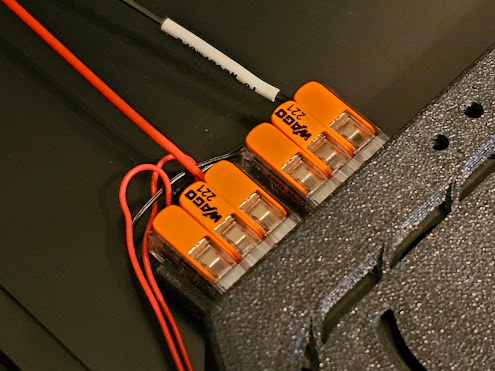
The second, more welcome change was the use of Wago lever nuts to simplify the wiring of the filter, eliminating the need to solder and crimp connectors on the standard Nevermore V5 Duo. The problem is, again - there were no instructions on what the hell these lever nuts were for beyond the labeling on the bag and the indentations on the back of the filter body for them to pop in.
This unfortunately was a trend I found with the Formbot kit. Putting together a Voron requires a fair amount of intuition, but when the kit builder deviates from the stock build by including mods and providing no instructions or references on how to install them, that's a problem.
Gantry Installation
The gantry is probably the most difficult, yet most crucial part of the build to get right. It must be as square as possible to ensure smooth motion in all axes, and the belts must not rub against the flanges on any of the pulleys. It's a pretty relieving feeling once you get past knocking over bearing stacks and rubbing your fingers raw turning the allen key over and over again putting these idler blocks together, but that's just the start of the headaches I had with this thing.
What you'll probably notice when you complete the gantry on it's own and start playing around with it; chances are, the motion of the Y-axis won't be very smooth. The side extrusions might narrow or widen as the XY gantry moves and the gantry itself might sit on a slight diagonal relative to the sides. This is known as racking, and it is an absolute must to "de-rack" the gantry before putting the printer into operation. If I haven't made it clear already, this is a tricky and time consuming process.
 |
| Zip ties are used to hold the gantry up while the Z-axis belts are installed. |
It's best to de-rack the gantry while it's installed on the frame, and that all the screws that tighten the blocks to the extrusions are slightly loose, including the four M5 bolts that connect the gantry to the Z-axis linear rails. Ideally, these four bolts should be able to slide right into place without touching the walls of their respective holes, and the X-axis rail should be perfectly perpendicular to the the two Y-axis rails, allowing for smooth movement without binding.
In short, I just kept everything loose and worked the XY gantry around until everything "settled" into place. I first made sure the Y-axis rails were parallel before tightening down the screws on the short extrusion in the back, and then straightened out the XY gantry by ensuring that both ends of it perfectly contact the front and back of the Y-axis without shifting. This wasn't a one and done ordeal. It took several tries before I was finally satisfied with the motion, and by that point I was damn near going cross eyed by looking at the thing for so long. But it's worth it!
Once the gantry is installed, this thing is finally starting to look like a functional 3D printer. It's already got some presence to it, and it's only about halfway finished.
Belts, Tap Sensor, and Toolhead Installation
With the gantry out of the way, it way time to start routing the belts and installing the toolhead to the linear rail carriage. The Formbot Pro+ kit includes Voron Tap for the printer's automatic leveling system. The version of Tap Formbot include didn't appear to have any documentation referencing it on Voron's Github, even though it was the most up-to-date STL available on the site.
The model of Tap referenced in the installation manual uses simple passthroughs to hold the belts in place. I'm assuming these weren't secure enough so they were replaced with clamps that use a press fitted M3 nut and screw to hold the belts in place.
 |
| Well, shit. |
Unfortunately, I ran into several problems with my example of this Tap revision. The clamps limited the vertical travel of the toolhead and prevented the sensor from tripping so I followed a move by YGK3D and cut a little bit off the clamp to restore some travel. While that gave the tool head more vertical movement, I might have cut a little too much off and my lower belt started to slip out. It also dragged on the front of the Tap body a bit, and the toolhead could get stuck.
To make matters worse, the clamps caused the back of the Tap body to blow out, causing all the belts to lose tension and slip. The M3 nuts were an awfully tight fit, and I think some over-extrusion might partially be to blame for it, but regardless, I had to fix the part if I ever wanted to get the printer working. I filled the holes with epoxy putty, sanded down the damage, and built up the front of the linear rail carriage with electrical tape to put more pressure on the back of the belts. I then zip-tied the excess before tensioning the belts. Thankfully, it held together.

The Clockwork 2 extruder pops into the top of the Tap body and is secured with two screws while the hotend portion gets pushed in underneath. The back has to sit flush against the Tap body or you might run into some nozzle dragging issues. The whole package is then secured together with the four screws through the front shroud. Once it's all bolted up, this thing hardly budges. I've seen some people demonstrate some degree of unwanted lateral toolhead movement because of Tap being a little more loose than solid carriage mount, but I didn't notice anything too bad.
It's worth noting at this point that Formbot didn't include the right pieces to attach one of the two included PG7 cable glands for a braided CANbus umbilical. While the included parts would have worked to add a wire supported umbilical without the braid, the little hooked support piece lacks the indentation for it to clear the USB-C port on the EBB, so I left it out and rolled with a sagging CANbus cable instead. While I could just print the correct part after the printer is finished, I'd still have to disassemble and reroute the entire CANbus line in order to fix it, and that sucks.
But all the mechanical parts are finally installed! Time to dive back into the electronics.
Trim Pieces and Electronics Bay
While not entirely necessary for the printer to operate, the bottom trim pieces give you some mounting points for switches, connectors, fans and more than anything - they just make the printer look cool as hell. I opted to put these on early since they'd give me a better idea of how to frame up the electronics bay and hopefully maximize the use of those dual 60mm fans.
 |
| One possible, but in my case unsuccessful arrangement of the electronics. |
The 250mm size Voron 2.4 unfortunately leaves you with a pretty cramped electronics bay with not a whole leeway forgiveness regarding component placement and wiring. Thankfully, the Manta M8P bypasses the need to make room for a Raspberry Pi and 5V power supply, and the EBB eliminates the need for a toolhead breakout board. So while I'm going to be pretty starved for space, it's nowhere near as bad as if I had a different mainboard.
This was another area where Formbot kind of dropped the ball on the Pro+ kit: they didn't provide any sort of wiring or component placement guide for the printer and it left me resorting to their old guides for the previous kit using the Octopus v1.1 alongside BTT's pinout diagram and
MagicPheonix's wiring guide for their Manta M8P equipped kits. Thankfully, Formbot does a very good job of labeling their wires, so that helped alleviate a lot of potential confusion
Paneling
The chamber of the Voron 2.4 is enclosed by acrylic panels sealed with foam around the edges. They're secured with simple brackets to facilitate easy installation and removal. Well, about as easy as M3 hammerhead T-nuts will allow anyways. I spent way too much time trying and failing to get these stupid things to rotate and lock into place, so it's no wonder one of the most popular mods for this printer is
snap latches that eliminate all that trouble.

However, the door hinges and magnet holders were yet another place where I ran into over-extrusion issues. The magnet holders simply couldn't fit in the slot of the extrusion without sanding down the walls, while the walls of the hinges were bulged out just enough for the printer's double doors to not close properly - at least not without closing the doors simultaneously to prevent them overlapping, but this causes them to bend inwards. Unfortunately I couldn't tell this was a problem until the doors were installed, so I'll probably end up removing these and file them down, or reprint them if I fail to remove the adhesive.
"Final" Software Configuration

I went back into Mainsail to finish setting up the printer configuration file, still using MagicPheonix's configuration files as a reference since their kits share a great deal of components with the Formbot kit. Now that everything was plugged in and powered, it fairly straightforward to test and ensure all my pins were set correctly by using Klipper's test commands and the default macros. I would just send the printer a command via the terminal, observe how it would react, and then just continue down the list until everything checked out.
I won't dive into the nitty gritty as I did have plenty of problems troubleshooting this configuration all on my own, but I will say that
Klipper's documentation website, along with any pinout diagrams of your boards will be your best friend as you navigate through this file. Worst case scenario, the Voron forum or Discord sever will point you in the right direction.

The one part I was never able to get working was the runout sensor, and I don't know if it's because my setup of it was incorrect or there's an actual fault with the switch. I would have to further test it, but it interfered so much with the printer's operation that I just omitted it entirely. Again, this is another area where Formbot could've provided some additional information, but didn't. That said, learning how to mess around with the configuration files is a very useful skill to have if you're getting into Klipper for the first time. Take every opportunity you can to learn more about how it works, and solving problems will become a whole easier.
First Calibration and Print
 |
| It's alive! |
Running first time calibration on the Voron 2.4 isn't much different than on any other printer. In fact, I'd say it's a lot easier. Since the bed is fixed in place, you don't have to worry about tramming the bed by hand. The four Z-steppers will automatically level out the gantry parallel with to bed, leaving the only things for you to do is set the Z-offset using a sheet of paper and PID tune the hotend and bed; all of which can be done from the touchscreen.
But now that I verified everything was working properly, it was time for the moment of truth. I loaded up some PETG, fired up OrcaSlicer and sliced the G-code for Voron's test cube using the default profiles. Then I sent it on it way through Mainsail; no SD cards required, and crossed my fingers as it ran it's startup routine.
It went without a hitch, and after a little over 40 minutes, I was left with an imperfect, but otherwise complete test cube. This is great because it gives me a clear idea of what I need to tackle next on the printer. But this first successful print off the Voron 2.4 is probably the coolest thing you'll ever see a 3D printer do for the first time, because you built it all yourself.
Conclusions
In closing, the Formbot Pro+ kit did exactly what it was supposed to: help me put together a Voron 2.4. That's something I would have never even imagined doing two years ago just getting into the hobby and here it is! While I did run into a handful of issues during the build, none of them stopped me from completing my very own, fully open-source CoreXY speed demon.
That being said, my biggest issue with this kit isn't really with the kit itself - it was the support and guidance that it lacked. Yes, the official Voron build guides should be all you need, but given the significant number of deviations to the stock Voron 2.4 build plan Formbot made, I would have expected at least a little direction on how it's all supposed to go together. They didn't provide a single guide that wasn't out of date, a list of STLs, configuration files, or at bare minimum; references to the sources they used that do provide these things.

I think this is the biggest difference between less expensive kit builders like Formbot versus the more expensive ones like LDO. While Formbot certainly didn't skimp out on their component choices either, LDO puts a hell of a lot more thought into helping their customers actually put together what they bought - deviations and all. I referenced both LDO's and MagicPheonix's guides fairly frequently during my build, because they were that much better than what Formbot offered - which was basically nothing.
Formbot has since officially released the Pro+ kit and updated their site with a wiring guide, component references, and STLs, but I wish all of this was already out there before they decided to start shipping these kits to buyers. Even then, I still think they can put more effort into giving buyers of it's kit some guidance how how to put certain parts of it together, and also up the attention to detail just a little bit on their printed parts.
Otherwise, the kit is awesome, and the value for money here versus an LDO or MagicPheonix kit is extremely compelling, especially if you just want the 250mm size. The printer it produced is a marvel, and the hours I've put on it since finishing it have been the most fun I've had with a 3D printer since I finally managed to dial in my Ender-3 S1 a while back. I'll post a more comprehensive review later on that covers more of the printer itself, but I'm already looking forward to getting years of use out of this thing and seeing how far I can push it.


Comments
Post a Comment